Continuous Welded Rail
Photos and story by Pat Durand
Continuous Welded Rail on the Alaska
Railroad
How Did They Do That?
During the 2003 summer construction season the Alaska Railroad installed continuous welded rail from Reeves to Matanuska. No one has seen a rail train come in on a barge. So how did they do that?
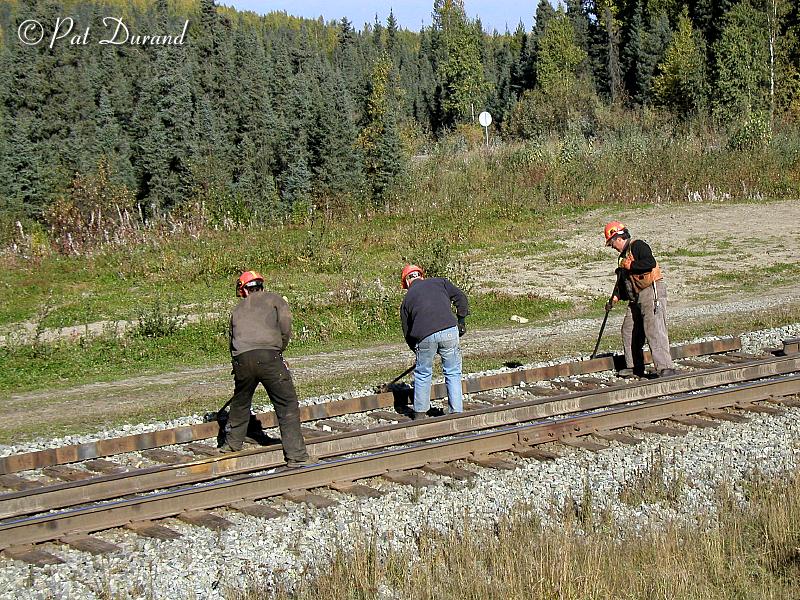
The ultimate recycle project has kept three crews busy from early May until November 21,2003 when they were finally frozen out by inclement weather. The job was done in phases with the coordination of an installation crew of 10 to 15 men, a three man crew on LC 109, and a six man welding crew from contractor, Schlater Rail Tech.
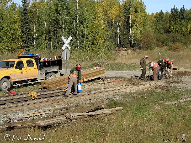
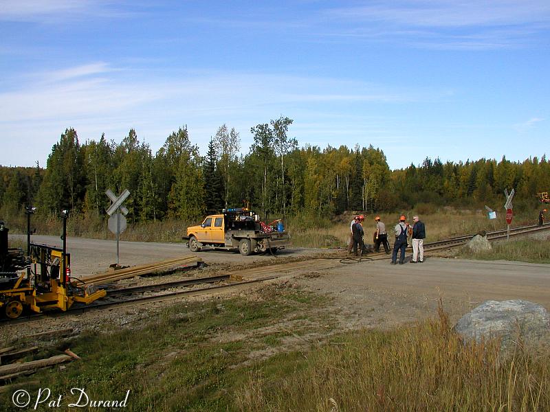
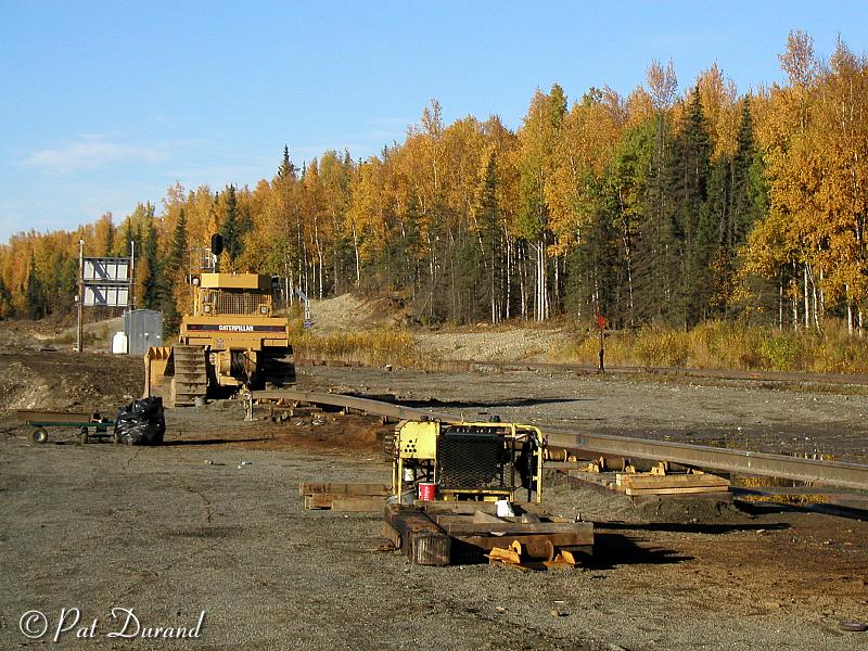
On August 1st, I was summoned by Jeff DeBroeck, the rail installation crew's mechanic, to observe the crew in operation as they worked over the Beach Lake road crossing at MP 134. 2 This location provided a safe observation point on the embankment overlooking the the job site where I would be well clear of the right-of-way. The weather and light were near perfect for photography.
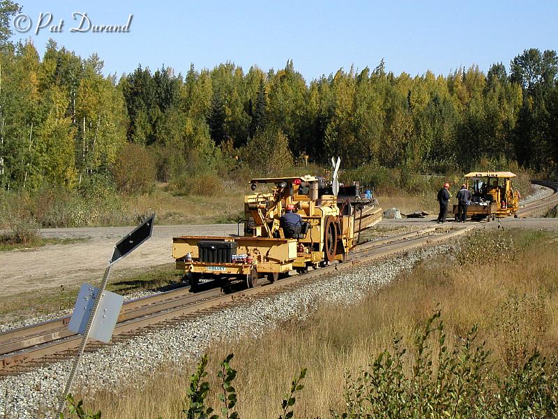
Two pieces of rail had been pre-positioned on the ties between the running rails at the job site. An 800 ft stick and a 550 ft stick were towed down the middle of the track from the welding station some three miles away at the Powder Spur MP131. More on that site later.
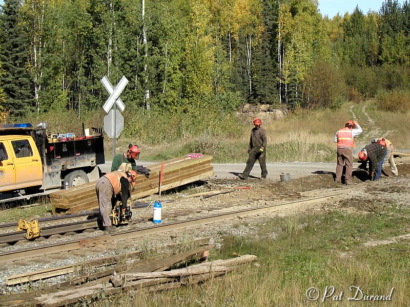
Because the grade crossing could only be out of service briefly and since only one rail is replaced at a time this requires some choreography resulting in a slower production pace than normal. New decking for the grade crossing was stockpiled earlier. The crew set about removing the old planking from each side of the west rail. The installation process, using on line equipment, requires that one running rail stay in place while the other is worked on.
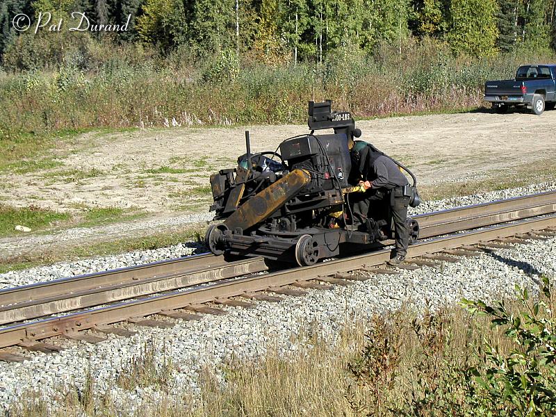
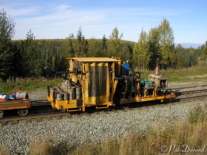
The first piece of equipment to arrive is the spike puller removing only the inside spikes on the west rail. Next is the magnetic spike pickup machine which recovers spikes and rail anchors and places them on a following trailer.
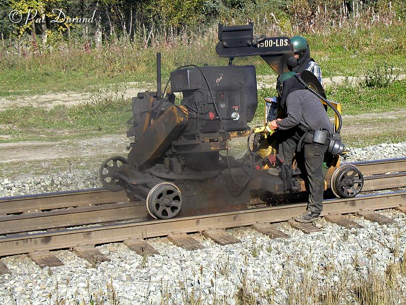
The light show arrives when the rail cutter stops about 10 inches short of a joint bar and the two man crew swings into action. A 28 inch abrasive cut off wheel suspended in a jig mount and powered by a 3 cylinder air cooled diesel engine makes a clean vertical cut through the rail. The saw is advanced past the joint bar and repeats the process, leaving about a three foot long battered joint still connected by the joint bars and bolts. In hot weather when the rail is expanded there can be a lot of bind on the saw resulting in as little as four cuts per blade. On this day it was about 70 F and they were getting good production. This is a dirty job and the crewmen wear positive displacement filtered air hoods to protect them from abrasive dust, metal cuttings and dust.
A three man crew with rail forks, roll the now free standing section of rail out from under the outside spikes. The rail and joint stubs are rolled into the clear about 6 ft from the tie plates. Any missing spikes or damaged tie plates are replaced at this time.
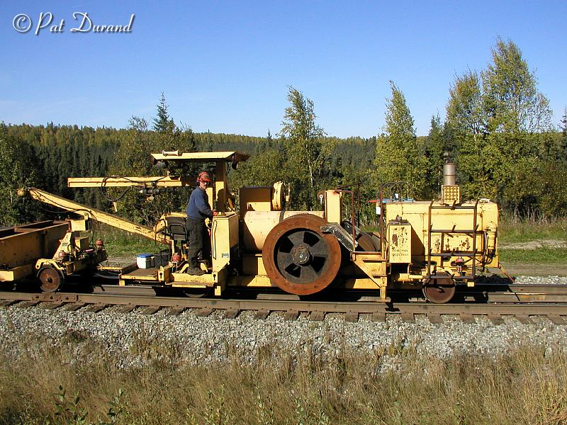
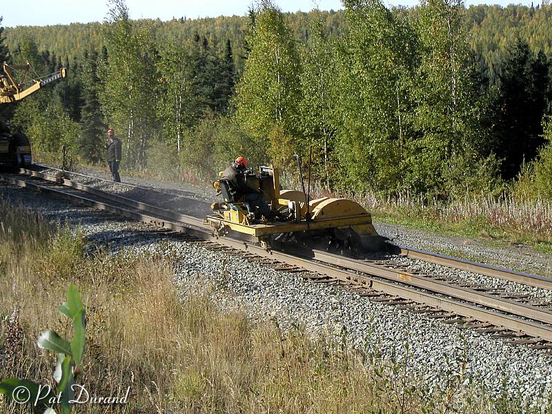
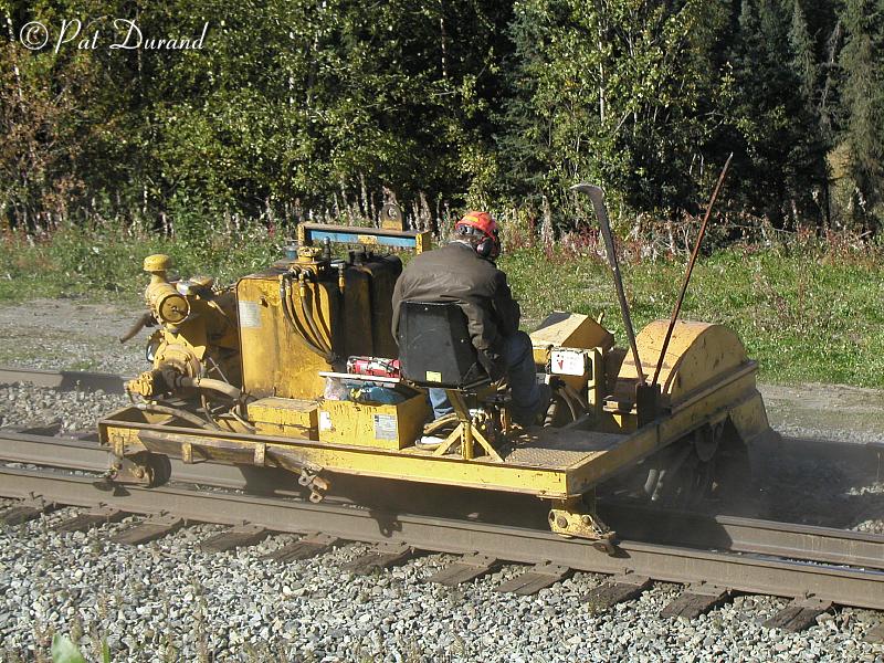
The cribbing machine arrives next and deserves some careful inspection. This combination flail and broom uses a rotary action to remove ballast from between the ties adjacent to the tie plates. It is self propelled on a single linked track riding down the middle of the ties and outriggers riding guided wheels on the remaining rail. It is noisy, dusty and kicks up lots of rock and debris which is windrowed just off the end of the ties.
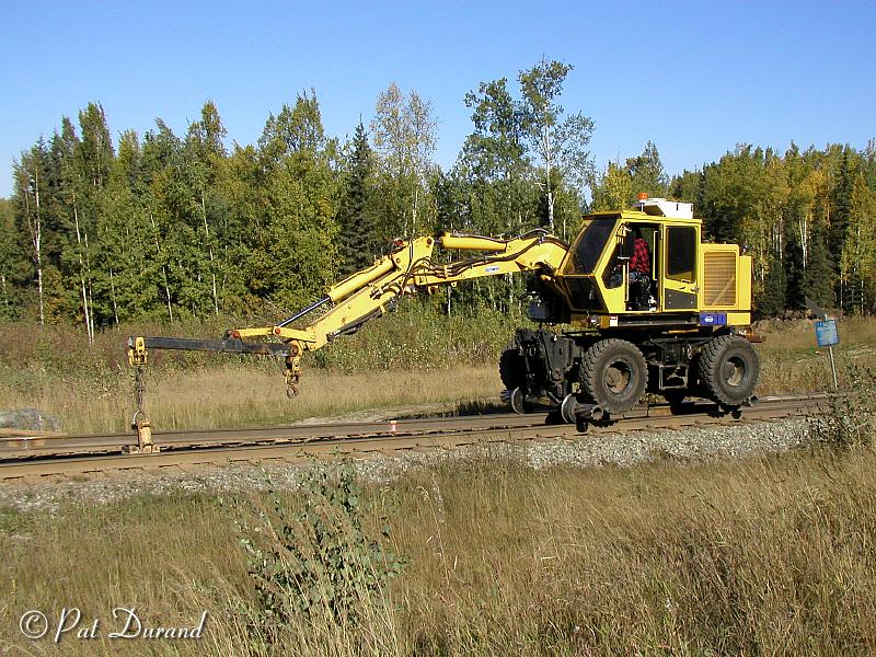
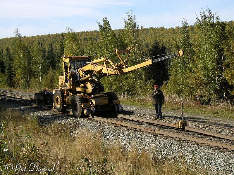
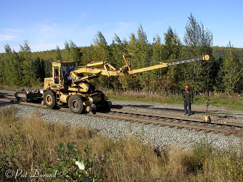
Now the rail bed and ties are ready to receive the replacement continuos rail which was pre-positioned on the ties near the opposite rail. Gentle application of brute force applied by a Petibone crane does the job. Rail guide wheels are lowered to the rail providing the proper gauge guide for the loose rail while the rubber tires are dropped to the exposed ties and ballast outside the rails providing traction. The welded rail is lifted slightly off the ties by a roller guide suspended from the crane boom. Careful manipulation of the guide with boom action and the forward advance of the crane guide wheels force the new rail into place on the tie plates and under the remaining outside spikes.
A ballast tamper then straightens ties and tamps up ballast to pull up any minor variance in tie elevation. A complete tune up will be done by the regular section crew after the second rail is in place.
Opinions of the suitability of continuous welded rail under Alaskan conditions were diverse. Experience of the BN and UP in the Northern tier have proven the success of this technology under even more extreme conditions than experienced in Alaska. The installations there get just as cold in the winter and hotter in the summer. The freeze thaw cycle is repeated many more times in those installations on longer tangents than we have here in Alaska. In Alaska, by comparison we freeze up, shrink up, and stay that way until spring.
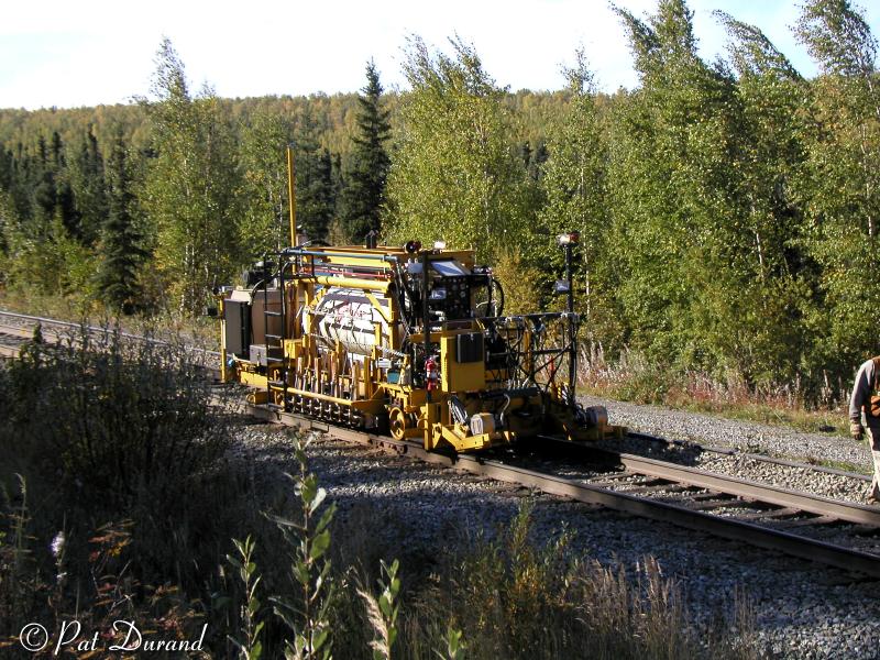
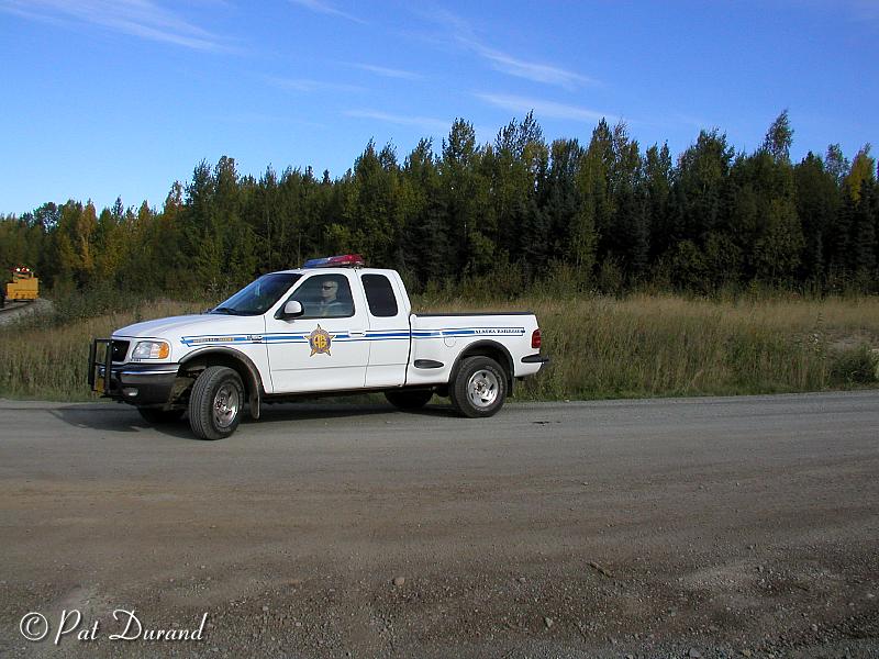
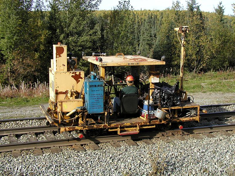
So how do you deal with expansion sun kinks and shrinkage pull aparts? Testing proved that the optimum rail temperature mean in this area is 86° F to minimize the potential of developing either problem. The “bomb” as it is affectionately called, is the answer. This self propelled rail preheater carries a large propane tank with a bank of burners over each rail. The rail being installed is heated to the optimum temperature expanding it in place. The stress of the expansion is relieved and sent forward down the unspiked rail by a vibratory weight that sets on top of the rail. Occasionally small fires are set in the debris left by the cribber so this is a safety monitor point. Alaska Railroad Security staff was never far away.
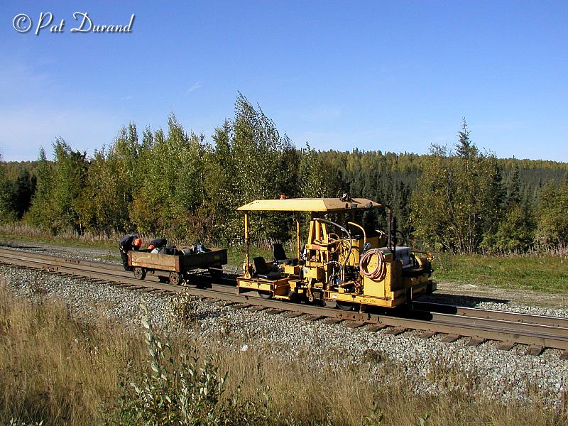
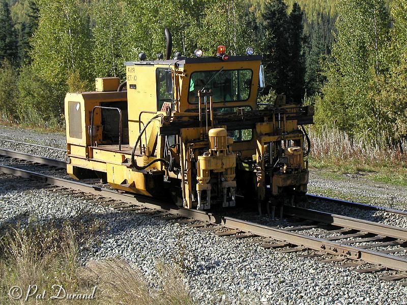
Before the rail cools down the two spike machines arrive working alternate ties setting the inside spikes. The anchor machines follow adding the spring anchors which keep the rail from creeping in the corners.
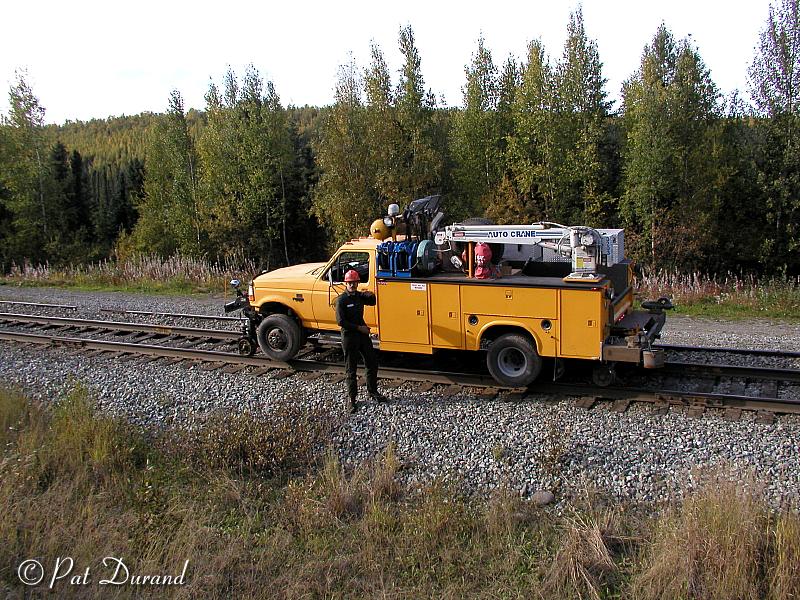
The final piece of equipment over the track will be Jeff DeBroeck with the mechanic’s truck on hy-rail gear.
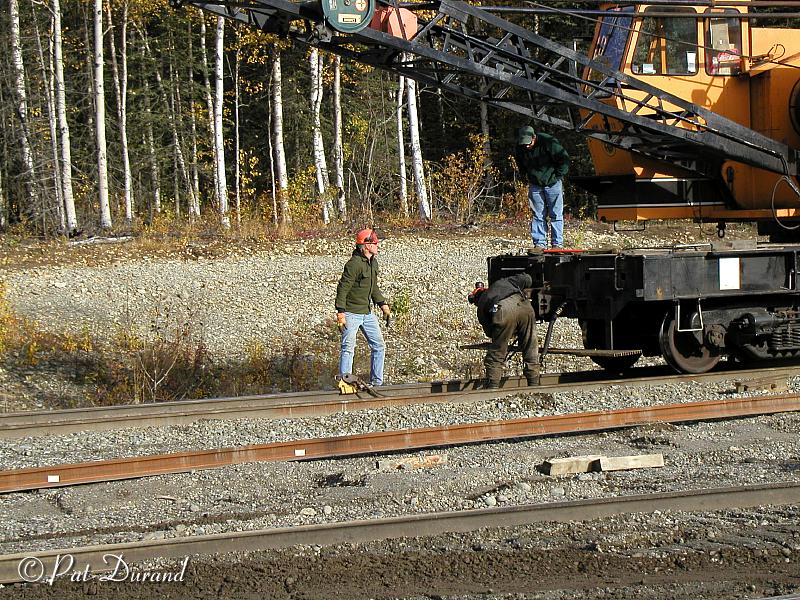
Mean while, the crew has been busy at the grade crossing drilling bolt holes in the next section of rail which will be connected by a temporary set of joint bars, eventually to be replaced by a thermite weld. The rail installation continues across the grade crossing and the new planking is installed in half of the crossing. The other half will be reworked when the opposite rail is replaced in a few days.
The crew quickly picks up pace after clearing the crossing and ends the day installing about 1300 ft of welded rail. This has all been accomplished on the busiest section of track on the Alaska Railroad during a work window between the morning gravel, scheduled passenger and freight trains, and the evening movements. Production on some days reached 4500 ft in straight track areas.
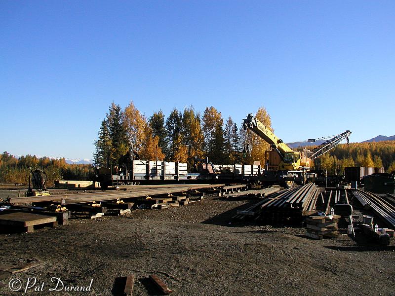
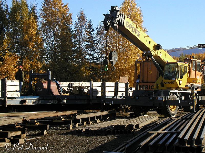
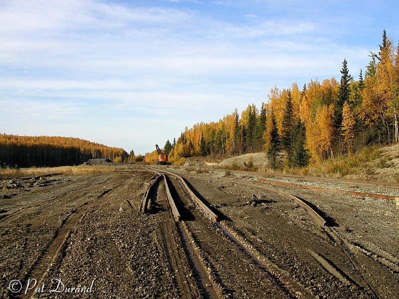
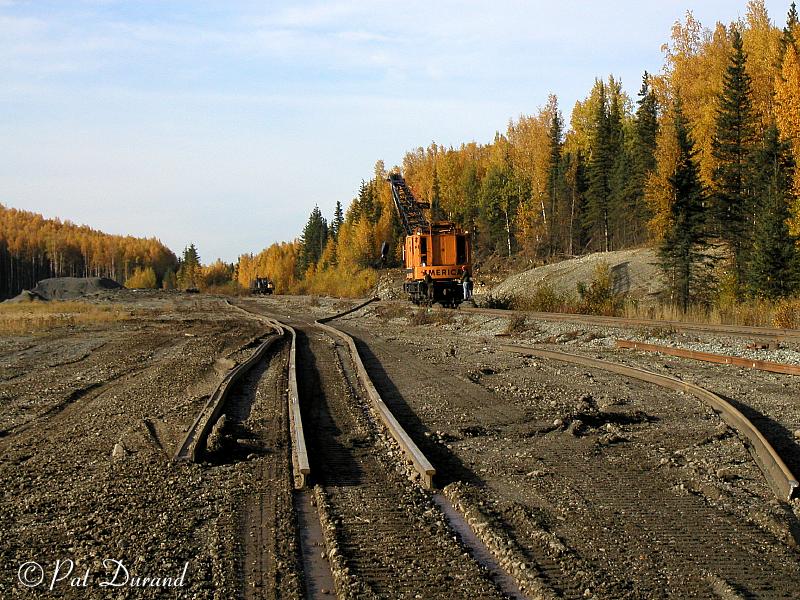
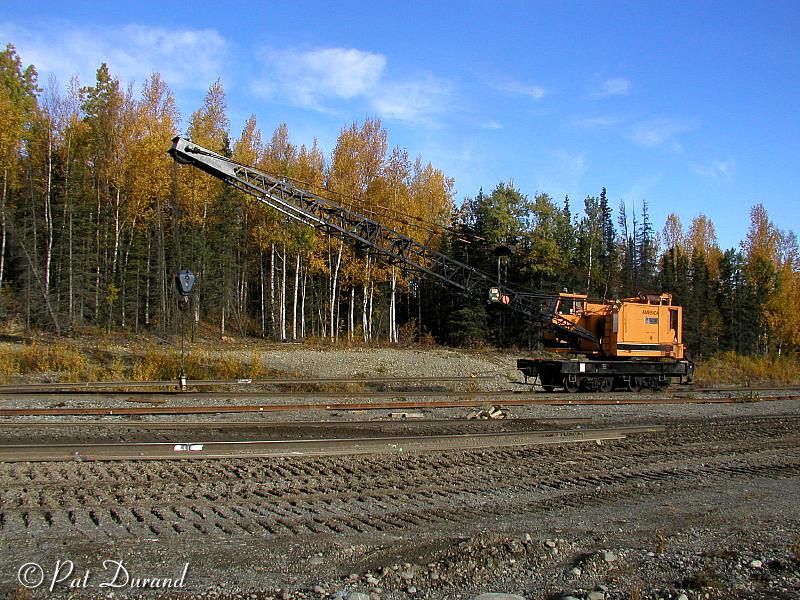
So where did the rail come from. In August the “Welding Plant” was located on the powder spur at MP131. Used sectional rail was picked up by LC 109 and transported on a purpose built flat car to the landing at the plant. A surge pile was built up on the landing and the rail moved from there to inspection and directly into line for welding.
A line of rollers extended from the welding station out toward the main line track where the end of the rail was connected to the winch cable of a D7 Caterpillar. A six man crew worked the plant and did prep grinding, welding, post weld grinding and final surface grinding. As the rail was extended the Cat towed it out until a finished 1000 ft string could be laid out parallel to the mainline track.
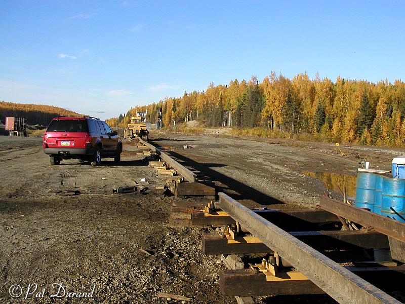
Like so many strands of ribbon the rail followed the contour of the ground awaiting transport to the installation site. No rail train here! After waiting for the morning gravel trains to clear the powder spur, LC 109 crane moved onto the main and proceeded to the far end of the ribbon rail. A roller rail guide suspended from the main boom line was attached to the ribbon rail and while working the boom the rail was lifted slightly and trailed behind the advancing crane coming to rest between the main line rails. The crew referred to this process as “rolling” rail. At the end of the ribbon rail a draw head was connected to the LC coupler. The roller guide was maintained in place to lift the rail end just off the ties. LC 109 sounded off and the string of ribbon rail followed down the main at about three miles per hour. Sliding across the ties and over switch wing rails proved no problem. Seeing is believing.
The railroad plans to continue this upgrade process recycling existing 115 Lb rail into quiet joint free track structures that will improve ride, reduce wear and increase efficiency. After both continuous rails had been installed, the regular section gang replaced ties as needed and did final alignment to bring the busiest section of the Alaska Railroad into top condition. Those fellows who started laying rail in Seward back in 1903 would be delighted with the progress.
Modelers note:
For model railroaders, here is an opportunity to put that Walthers crane to
work. Find a siding and establish a “Welding Plant”. On the off
days you can store all the track equipment on the same siding so the mechanic
can work on it and the guy from Wish and Wash can pressure wash the track saws
and spike machines.
Added by Rich Hozapfel, Alaska Railroad extra-gang foreman on 7/20/04:
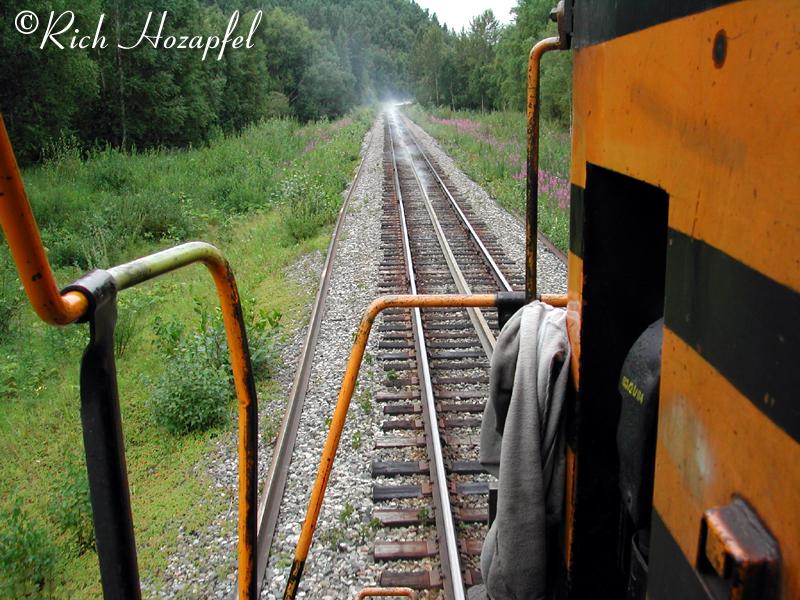
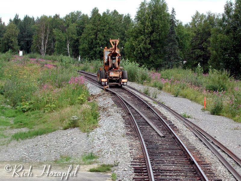
Here's a couple of photographs of my work train dragging 1000 foot strips of continuous welded rail for installation near Talkeetna! The first photo is dragging rail strips with my locomotives, the second photo is the Wheel Crane WC2 threading the rail to the shoulder of the track.
|
|
Dragging the rail strips doesn't tear up the
ballast because it slides on the ties, but as you can see in my photo the rail
gets warm enough to smoke the ties. We do drag the rails all the way to where
they will be installed, but we won't drag them more than about eight miles because
of the heat caused by the friction. The CWR foreman Rick Simmons checked one
of the rails we had dragged about 3 miles and its temperature was 360 degrees.
Page created 11/28/03 and last updated 7/20/04